Product Detail
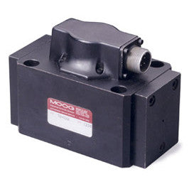
78 Series
Quick Overview
DIRECT OPERATED SLOW CONTROL SERVO VALVE WITH ANALOG INTERFACE
Mounting Surface: Unique to 78 Series
Max Pressure: 3000 PSI (210 bar)Rated Flow Rate: 20 to 40 gpm (75 to 150 l/min)
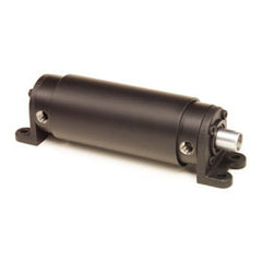
The 78 series is part of the Moog family of Mechanical Feedback (MFB) Servo Valves. They are throttle valves for 3 and 4 way applications. This series has a high performance, two-stage design that covers a range of rated flows from 75 to 150 l/min (20 to 40 gpm) at 35 bar (500 psi) valve drop per spool land. These valves are intended for position, speed, pressure, or force control applications that require high dynamic response. The 78 series MFB offers high dynamics, high resolution and low hysteresis due to its low friction double nozzle pilot stage.
The design is simple and rugged for dependable, long life operation. The output stage is a closed center, 4 way sliding spool. The pilot stage is comprised of a symmetrical, double nozzle dry torque motor. The 2nd stage spool position is controlled by a carbide tipped feedback wire. The carbide ball on the end of the feedback wire is a mandatory design requirement that ensures high accuracy, reliable operation, and long service life. All of our servo valves are known for high accuracy and reliable operation even in the harshest industrial applications.
This family of valves is considered a flow control servo valve with an analog interface, but does not contain integrated electronics. The options in this series include standard and high response, special null (spool) cuts, seal materials, and connectors. Intrinsically safe and flameproof designs for use in hazardous environments are also available with specific models certified to FM, ATEX, CSA, and TIIS (Asian) standards.
All of our valves are backed by Moog Global Support, our promise to provide world-class repair and maintenance services delivered by our trained technicians. Each valve possesses a long life design, controlled by proven servo valve technology that has an outstanding history of 60 years of meeting the motion control needs of our customers. All of this makes Moog servo valves the best choice for your hydraulic motion control requirements.
The 78 Series is proven technology that performs reliably in machines where high performance, stability and accuracy are required. Moog’s Mechanical Feedback Valves are designed to provide high reliability and long service life. The current technology reflects over 60 years of experience of servo control in some of the world’s most demanding environments.
The 78 Series Flow Control Servo Valve consists of a polarized electrical torque motor and two stages of hydraulic power amplification. The torque motor armature extends into the air gaps of the magnetic flux circuit and is supported in this position by a flexure tube. The flexure tube acts as a seal between the electromagnetic and hydraulic sections of the valve. The 2 torque motor coils surround the armature, one on each side of the flexure tube.
The flapper of the first stage hydraulic amplifier is rigidly attached to the midpoint of the armature. The flapper extends through the flexure tube and passes between 2 nozzles, creating two variable orifices between the nozzle tips and the flapper. The pilot pressure is controlled by the flapper/nozzle variable orifice and is in turn fed to the end areas of the second stage spool. This action creates a differential pressure from one end of the spool to the other and results in spool displacement. The spool displacement causes a force in the feedback wire which opposes the original input signal torque. Spool movement continues until the feedback wire force equals the input signal force.
The second stage is a conventional four-way spool design in which output flow from the valve, at a fixed valve pressure drop, is proportional to spool displacement from the null position. A cantilever feedback spring is fixed to the flapper and engages a slot at the center of the spool. Displacement of the spool deflects the feedback spring which creates a force on the armature/flapper assembly.
Input signal induces a magnetic charge in the armature and causes a deflection of the armature and flapper. This assembly pivots about the flexure tube and increases the size of one nozzle orifice and decreases the size of the other.
| Rated Flow Per Spool Land (Δ 1000 psi/70 bar) | 20 gpm | 75 l/min | |
| 30 gpm | 115 l/min | ||
| 40 gpm | 150 l/min | ||
| Max Operating Pressure | F | 3000 psi | 210 bar |
| Viscosity Range | 42 to 5787 SSU at 100 °F | 5 to 1250 cSt | |
| Temperature Range | -40 to +140 °F | -40 to +60 °C | |
Product Specifications
Related Products