Product Detail
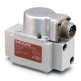
G77X & 77X series
Quick Overview
DIRECT OPERATED FLOW CONTROL SERVO VALVE WITH ANALOG INTERFACE
Mounting Surface: ISO 10372-02-02-0-92 (G771/771)
ISO 10372-03-03-0-92 (G772/772)
Moog Standard
Rated Pressure Rate: 1 to 15 gpm (4 to 57 l/min)
The G77X/77X Series flow control servo valves are throttle valves for 3 and preferably 4-way applications. They are a high performance, 2-stage design that covers the range of rated flows from 4 to 57 l/min (1 to 15 gpm) at 210 bar (3000 psi) valve pressure drop per spool land.
The output stage of the valve is a closed center, four-way sliding spool. The pilot stage is a symmetrical double-nozzle and flapper, driven by a double air gap, dry torque motor. Mechanical feedback of spool position is provided by a cantilevered spring. The valve design is simple and rugged for dependable, long life operation.
These valves are suitable for electrohydraulic position, speed, pressure or force control systems with high dynamic response requirements. The G77X/77X is ideally suited for applications where superior dynamics are a must.
Intrinsically safe valve versions are available for use in applications with potentially hazardous environments. Specific models are certified to FM, ATEX, CSA, TIIS and IECEx standards.
The G77X/77X Series is proven technology that performs reliably in machines where high performance, stability and accuracy are required. Moog’s Mechanical Feedback Valves are designed to provide high reliability and long service life.
The G77X/77X Series Flow Control Servo Valve consists of a polarized electrical torque motor and two stages of hydraulic power amplification. The motor armature extends into the air gaps of the magnetic flux circuit and is supported in this position by a flexure tube. The flexure tube acts as a seal between the electromagnetic and hydraulic sections of the valve. The 2 motor coils surround the armature, one on each side of the flexure tube.
The flapper of the first stage hydraulic amplifier is rigidly attached to the midpoint of the armature. The flapper extends through the flexure tube and passes between 2 nozzles, creating two variable orifices between the nozzle tips and the flapper. The pressure controlled by the flapper and nozzle variable orifice is fed to the end areas of the second stage spool.
The second stage is a conventional four-way spool design in which output flow from the valve, at a fixed valve pressure drop, is proportional to spool displacement from the null position. A cantilevered feedback spring is fixed to the flapper and engages a slot at the center of the spool. Displacement of the spool defects the feedback spring which creates a force on the armature/flapper assembly.
Input signals induce a magnetic charge in the armature and cause a deflection of the armature and flapper. This assembly pivots about the flexure tube and increases the size of one nozzle orifice and decreases the size of the other.
This action creates a differential pressure from the one end of the spool displacement causing a force in the feedback wire which opposes the original input signal torque. Spool movement continues until the feedback wire force equals the input signal force.
| G771 | G772 | G773 | |||||
| Rated Flow (Δ 500 psi/35 bar per land) | 1 gpm | 4 l/min | 5 gpm | 19 l/min | 15 l/min | 57 l/min | |
| 2.5 gpm | 10 l/min | 10 gpm | 38 l/min | - | - | ||
| Max Operating Pressure | F | 3000 psi | 210 bar | ||||
| Viscosity Range | 42 to 5787 SSU at 100 °F | 5 to 1250 cSt | |||||
| Temperature Range | -40 to +140 °F | -40 to +60 °C | |||||
Product Specifications
Related Products